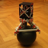
Ball Balancing Robot
I’ve built a balancing robot on two wheels before (http://ftcommunity.de/categories.php?cat_id=2741), and announced I was working on one that could balance on a ball (http://ftcommunity.de/details.php?image_id=36900). That turned out to be a whole lot more difficult. Finally, I managed to get something reasonable to work.
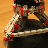
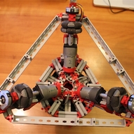
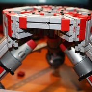
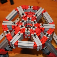
In order to have a robot move around on a ball you need so-called ‘omni wheels’, that can be driven in one direction and float free in the orthagonal one. With 3 motors you can control lateral movement in two directions, plus a rotation. With that, it is essentially a matter of running the same sensors and algorithms that I used for the robot balancing on wheels, but now in two independent directions X and Y.
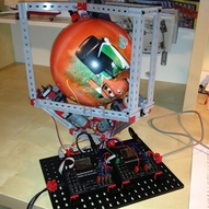
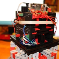
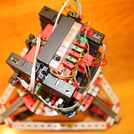
For sensors it uses:
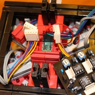
- a rate gyro, to determine the angular speed of falling, connected through the I2C interface to the TX.
- an accelerometer, to determine what is ‘up’, also connected through the I2C interface to the TX.
- a magnetometer, acting as a compass to give it a sense of direction. This is not needed to balance, but it will allow the robot to stay in position and drive. This is also interfaced to theTX using the I2C interface.
- The ft remote control unit is used to allow you to control the robot with the FT infrared remote controller. Unfortunately the TX (unlike the Robo Interface) has no infrared receiver, so to use the remote controller, I simply connected the three motor outputs of the remote controller unit to TX inputs in analogue 10V mode. When operated, they give a nice reading between 5-9V that can be used as inputs to the controller to drive the robot.
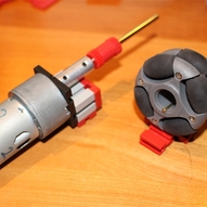
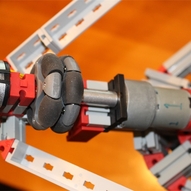
- a quad encoder sensor on each axle to measure rotation of the ball and thereby the lateral speed of the robot. Unfortunately there is no good fischertechnik solution for this, so I used an IC on a home-designed print to decode the quad encoder signals in up and down counters that are fed into theTX counter inputs.
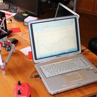
The software is written in C and running on the TX. It operates on a 100Hz cyle. Every 10ms the sensors are read, the data filtered and the motor PWMs calculated and adjusted using a PID controller. The TX has plenty of power to do the math. This is quite amazing, since there are a lot of calculations done every 10ms. By distributing the required work over ten ‘progtic’ cycles, it all fits easily within the allowed 500 microsecond budgets.
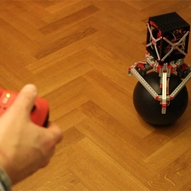
Some pictures below, but this is all about movement, so you need to see the video of the balancing robot here: http://www.youtube.com/watch?v=QuTUYofiwcE
In dieser Galerie gibt es 20 Bilder: