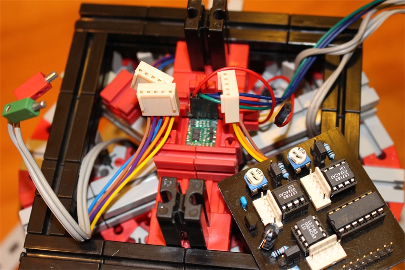
Decoder and sensors
Hochgeladen am 18.1.2014, 17:48 von winijenh. 5 / 20
This is a self-designed decoder print with 3 LC7183 decoders. It also generates the 5V needed for the quad encoders and the gyro/accelerometer board, which is the small green thing that can be seen in the middle of the construction. That is a MinIMU-9 v2 breakout board by Pololu (http://www.pololu.com/catalog/product/1268) that houses a gyro, a combined accelerometer/magnetometer (for compass function) and a 5V I2C level shifter, so that it can be connected directly to the TX’s 5V I2C connector.
The gyro is needed to provide fast rotational speed information. As gyro’s have a bias that drifts over time (that is, even when not in motion, they will typically indicate a small degrees per second rotation which may change over time) an accelerometer is needed to correct the bias and provide the robot with a sense of where ‘above’ and ‘below’ are. I use a simple Kalman filter to maintain a filtered bias and robot angle. The unbiased rotational speed is used unfiltered.
The TX I2C interface only allows 2 byte read/write operations at a time. I needed to read at least 6 bytes every 10ms (3 gyro axis of 2 bytes each) and 12 more bytes less frequently (6 bytes accelerometer, 6 bytes magnometer). The only way I could fit that in was to use the trick to start reading the next 2 bytes while still in the callback procedure that the TX calls to report that the previous 2 bytes are read, rather then wait for the next ProgTic to start the next read. Not sure if that is really supported, but it works. I read about that possibility in the forum I think, but can’t find it now. It greatly speeds up the I2C communication speed.