Scope Demo
Hochgeladen am 23.1.2009, 08:29 von Ad. 20 / 20
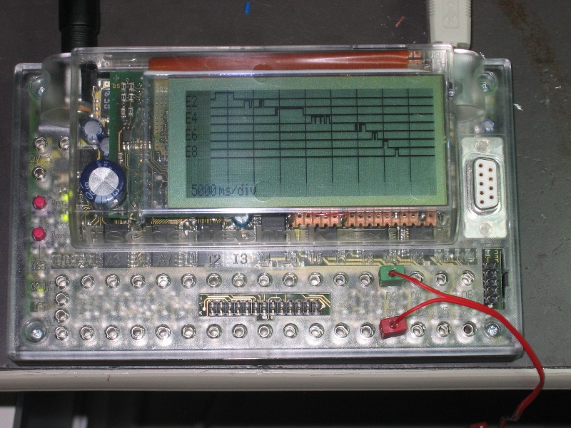
A demo of use as a chart recorder. Here showing the (past) status of the 8 inputs.
Stefan Falk (23.1.2009, 14:19:45)
Wow. How is this display programmed? C? Thkais-Basic?
Best Regards, Stefan
Ad (23.1.2009, 16:00:06)
It’s programmed with Renesas C. I haven’t found a way to link it to RoboPro and I’m not a big fan of Basic. Besides the HEW environment with FtLoader works very convenient. If there is a demand I could help with setting up a Basic library. I would rather have an interface to RoboPro however but that will not be easy without the help of RoboProEntwickler.
schnaggels (24.1.2009, 23:36:58)
Hi Ad,
another very nice job you did! The display seems to be fast enough to follow the bus signals? Thkais had to add some
I could imagine having a small C program for the display running besides the firmware, with manipulating the interrupts this could work without RoboPro notices it or? The data transfer between RoboPro and the C program could be done via a special memory area where RoboPro stores the content of a list as example? For sure not very fast, maybe good enough to control some functions like “show in/out” or similar.
Could have a chat with RIE and RPE to ask for possibilities if you want? Extra firmware or RoboPro functions will not follow for sure…
Have to order the Pollin display now :)
Thomas
Ad (25.1.2009, 19:35:10)
Hi Thomas,
Speed is critical, and no, it’s not fast enough. Critical are the pulse width (WR, RD) and the hold times. Read is more critical than write but we could operate the display with only write operations. Sufficient write pulse width can be achieved with an extra waitstate (can be set in software). The other constraints can only be met by slowing down the clock. According to the datasheet of the LH155 (the display does not have that controller but a similar one), a clock of 10MHz and 2 waitstates should be ok for both reads and writes. Of course we only need to use these when we access the controller. I tried however with 20Mhz clock and 3 waitstates and I could both read and write (@3.3V), so I use this (2 waitstates did not work for me).
I was thinking about a solution with a timer in order to keep some simple process running. Start my own main program in flash2 in order to hook my own processes and then start the robopro program in flash1. There is no guarantee however that this works because the roboint may make a distinction between C and robopro programs, so I may not be able to invoke the robopro program, or nevr get control back because robopro ‘stole’ it.
Ad
schnaggels (26.1.2009, 15:56:00)
This was about my idea, getting the interface to run a second program within a misused interrupt parallel to the RoboPro. As the interrupt table can be stored in RAM a failure shouldn’t destroy the interface :) Unfortunately I’m not (yet) so deep in Renesas µC programming with C, maybe you can have a chat with thkais?
Am I right that the connection plan is only a block diagram? At least the DC up-converter needs some additional parts to run… The display itself is direct connected to the data and address bus, no buffer or other logic needed?
Thomas
Ad (26.1.2009, 21:54:57)
There are no buffers, the DC converter is the same as in the pollin demo circuit except that I didn’t make the voltage adjustable. Here is the link: http://www.pollin.de/shop/downloads/D120487B.PDF The component values are not critical, R1 should be low enough and the ratio R3/R4 should be ok for 15V. I’m trying to analyse what robopro does when it starts a program and which resources (memory, timers) it uses. But it’s a lot of work, might just as well try it and pray for luck.
schnaggels (12.6.2009, 09:27:53)
Looks like my idea came true :) http://www.ftcommunity.de/wiki.php?action=show&topic_id=35
Modelbauer (13.4.2013, 14:32:53)
Thats very good.