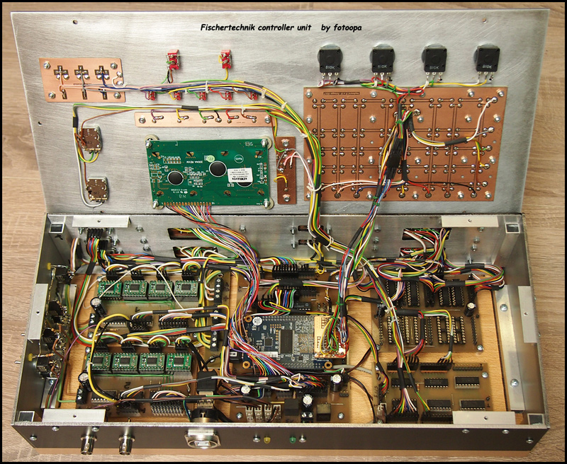
Controller intern view with FPGA
Hochgeladen am 27.10.2017, 19:37 von fotoopa. 26 / 31
Schlagworte: FPGA, controller, hardware.
Internal view controller fotoopa with FPGA module.
uffi (28.10.2017, 02:34:15)
Das sieht ja toll aus! Und sehr aufwendig… was kann das denn alles? Sehe ich da links 8 Module für Schrittmotoren? Bitte noch mehr Detail-Fotos, auch von den Anschlüssen hinten…
fotoopa (28.10.2017, 09:21:00)
Yes there are 8 modules for engines type TB6612 = 16 motors full control. On the right is a servo module available for max 64 servos, For 32 servos, connections are already provided at the rear. All power supplies come in on the left.
There are 3 serial connections that go to additional interface boxes. Those external boxes contain the inputs of the detectors, the rotary encoders, the optical encoders, the magnetic detector, etc. The first box has 24 inputs and 24 outputs. The 2nd box contains 48 outputs. Each output has 0 or 5V level via a 220 ohm resistor. Works for all leds or 7 segment displays. Protocol is about SPI input / output at 500KHz and is unlimited in length. There are 128 Neo color leds fitted in a loop. These leds provide information for status of the Fischertechnik parts and the position of the servos (left pos = green, centre pos =red, right pos = blue).
Each servo has max 4 positions (1 powerup pos, 1 left pos, 1 middle pos en 1 right pos). They are preset but can also be read and changed by the user via 2 Rotary encoders on the frontplate. The LCD 4x20 char give info about the program, motor speeds, direction etc. Keyboard is a matrix 5x8 = 40 keys. The FPGA is programmed via the USB connector on the front. There are also 2 connectors for a scoop to test the program. The FPGA can output any desired signal about these two connections.
This project is to build a super XXLL dynamic “Kugelparcours”. A lot of extra info is also available on my Flickr (see my profile)